This is part 2 of a multipart blog series on the Virtual CTO project: A digital reconstruction of the CTO measurement train commissioned by the section Railway Engineering at Delft University of Technology. In part 1 of this blog series I covered the process and results of making LiDAR scans of the train, both outside and inside. In this part I continue with describing the CAD modeling process.
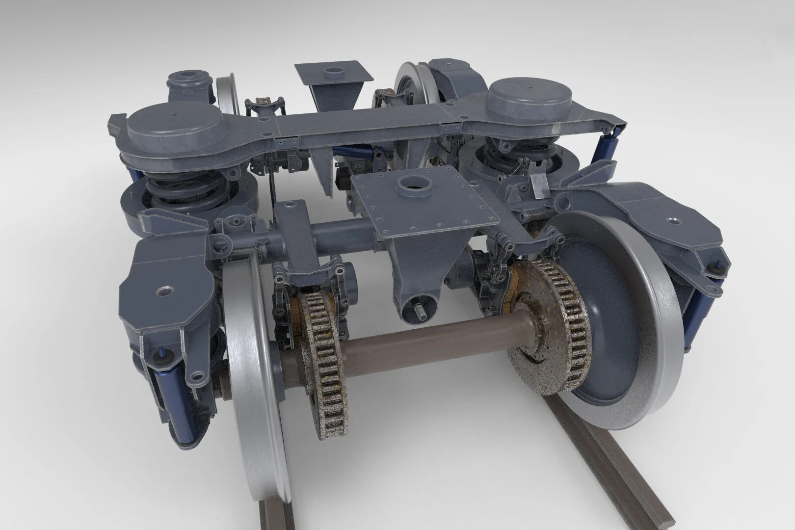
CAD model of Y32 bogie (work in progress)
I started modeling the bogies of the CTO measurement train late 2017, between the first and second scan session. And although the models aren’t completely finished yet, I will show the current status here and explain how I got there.
REFERENCE
Most modern rail vehicles run on bogies. A bogie provides some of the most essential functions to the rail vehicle: It carries the load, it transmits the traction and braking forces, it guides the train in a safe manner and it smooths out track irregularities. In essence a bogie is a metal frame to which the axles and wheels are attached. Usually, two bogies are fitted to each carriage or wagon, one at each end. Because of their importance in railway engineering, we decided that the CTO bogies needed to be modeled in detail and by part, to provide a solid foundation for both engineering calculations and a range of educational realtime 3D visualization options.
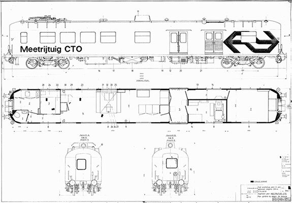
Construction drawing library
The CTO measurement vehicle is a former postal vehicle that was converted in the 1980s into a measurement vehicle for the Center for Technical Research (CTO). The original P 7918 postal vehicle was built in 1952 at Allan in Rotterdam. In the renovation, the original bogies were replaced by Y32 bogies, and a Faiveley AM56 pantograph was mounted on the roof as well as a dome with a TV camera in it to record the behavior of the pantograph. A large part of the technical drawings of this renovation have been preserved, especially for the Y32 bogies. These drawings were the starting point for reconstructing the bogies in 3D, and are now part of the construction drawing library I setup in the Fusion Team Hub for this project.

Reference photo library
The second scanning session in April 2018 offered me the ideal opportunity to shoot many reference photos for the reference library. Because the bogies had to go into maintenance, I had perfect access to them as well as to the entire chassis and the complete interior.


MODELING
There is no one modeling software approach optimal for all situations. In general 3D modeling for games and visual effects is done in ‘direct modeling’ software like Maya, 3ds Max, ZBrush and others (most often using polygons). While I’m using some of these tools as well for creating realtime 3D content, in part also for this project, I chose to model the Y32 bogies in a (history-based) parametric CAD environment as it is much better suited for creating dimensionally accurate 3D models with maximum flexibility in application possibilities.
Fusion 360 parametric modeling interface with pre-weld version of the bridge piece from the Y32 bogie disc brakes
To demonstrate the principle of history-based CAD modeling, the clip below shows a timeline animation of how the Y32 bogie control arm was modeled inside Fusion 360:

Why Fusion 360
For mechanical engineers SolidWorks has long been the de facto standard in CAD software, which is also why it’s widely used at Delft University of Technology. However in the past years Fusion 360 has been rapidly increasing its market share to the point it seems to have taken over the lead position from SolidWorks in 2018, while the market share of Fusion 360’s big brother Inventor has quickly decreased. (source: CNCCookbook 2018 CAD Survey).
So when we had to choose the CAD package for this project about a year ago, it was basically a SolidWorks vs Fusion 360 decision. The table below shows a comparison between both packages, which is by no means exhaustive.
| Criteria | SolidWorks | Fusion 360 |
|---|---|---|
| Operating system | Windows only | Cross platform (Windows and Mac) |
| Cloud integration | Runs on a local machine or server (and in a browser with limited features). Working on multiple machines without PDM software on a server is a hassle (and can become critical for assemblies with referenced parts) | Full cloud based solution with continuous data syncing to an online A360 hub from which team collaboration on designs can be as easy as granting someone access to your design. Any user can be a member of an unlimited number of Team Hubs, where you can review designs, track updates and add comments. Design files can be viewed within the browser and on any mobile device. (Cloud features require an internet connection) |
| User interface | Classic look, crowded and intimidating interface, but pie-menu and programmable keyboard are powerfull. | Very user-friendly intuitive interface and workflow that is adapting to your current task. Interface also works well on smaller screens and can be customized to improve your efficiency. |
| Modeling tools | Very exhaustive set of functional tools for both parametric and direct modeling, but no sculpting. Tools and features have all the options you can imagine, but some can be a bit time-consuming to use though. | Large set of easy to use 3D modeling tools for both parametric and direct modeling as well as sculpting. Great tools for quickly executing and exploring ideas. However tools often leave something to be desired, but more depth is being added continuously. |
| Assembly tools | Completely assembly-driven, referencing in parts in assemblies is required. Large assembly load modes: Resolve, Lightweight, Large Assembly Mode, Large Design Review | Allows different components to be built in the same file, but can also work assembly-driven with referenced parts. No specific large assembly load modes |
| Simulation tools | Very advanced simulation and analysis options, evaluates both linear and non-linear responses, composite materials and dynamics. | Intermediate and expanding toolset, and easy to use. |
| Manufacturing tools | Top of the line tools for creating production-ready CAD models. | Intermediate and heavily expanding toolset, and easy to use. |
| Import and Export | All happens on your own machine. About 35 file formats supported. No mesh support. No referencing of 3rd party CAD files, import only. | Files have to be uploaded to A360 before they can be imported. About 35 file formats supported. Export options somewhat limited. Supports meshes as well, but tesselation quality on export is limited. AnyCad technology makes it possible to import SolidWorks and other 3rd party CAD files as reference models. Changes to those models will update in Fusion 360 seamlessly, making collaboration much easier. |
| Workflow to UE4 | Unreal Datasmith directly supports native SolidWorks files. | Datasmith doesn't support native Fusion 360 files, use STEP file instead. |
| Learning curve | Steep learning curve | Very easy to learn |
| Updates | Yearly major releases, quarterly service packs via installer | Continuous automatic feature updates and bug fixes |
| Price | Tiered pricing structure, pay more for more features. Packages are offered between $3995 and $7995, with annual maintenance between $1295 and $1995. Only available via local resellers after personal quote. Student edition exists but trial versions are hard to get. | One price tier at $495 per year with unlimited upgrades, discount possible. Free 30-day trial. Free licenses for teachers, students and non-commercial use. Free to use for small businesses with revenue under $100k. Available directly from Autodesk website. Edit 2020: Some Simulation and Manufacturing tools now require Cloud Credits to be used despite being listed as available product. |
Comparison between SolidWorks and Fusion 360
In the end SolidWorks was just too expensive for a freelancer who doesn’t focus on CAD all the time, but rather uses it as a part of his complete toolset. Together with the impressive set of features Fusion 360 offers compared to SolidWorks for so little money, and considering the fact that with AnyCad it should be easy for the TU Delft to integrate Fusion 360 into their current CAD workflow, the choice for Fusion 360 was actually very obvious (at that point I wasn’t aware of the performance differences for large assemblies).
Workflow considerations
Fusion 360 provides an interesting alternative for the ‘distributed design’ workflow that traditional CAD software like SolidWorks enforces. Rather than having to create separate design files for every part and assemble the entire design in an assembly file, Fusion 360 also offers a ‘multi-body design’ solution with a structure of bodies and components within a single file, that should be able to do the same. In order to understand how to use either of the two workflows or a combination of both, it is very important to understand the differences between bodies and components in Fusion 360 first. The table below shows these differences side by side.
| Bodies | Components | |
|---|---|---|
| Definition | a body is any continuous 3D shape that won’t require any associated motion | a component is a position and motion independent part of an assembly within a single design environment |
| Feature association | bodies share the origin, coordinate system and timeline with the top-level assembly | components have their own unique origin, coordinate system and timeline whereas bodies do not by associating all features with a component, that component can quickly be exported into any new design |
| Parenting | a body can't contain bodies or components | a component can contain bodies as well as other components this is how designs get organizational structure in terms of what is a single part (body or component), sub-assembly (component), and assembly (design) any level of depth is allowed to match the real life assembly |
| Linking | a body can't by linked from another design file on its own | a component can be linked from another design file, linked components update in all referencing designs whenever they are edited, linked components do not compute, they are read-only |
| Copy/paste behaviour | if a body is copied and pasted, changes that are made to one body will not affect the other | if a component is copied and pasted, changes that are made to one component will affect the other depending on the paste command used |
| Identification | the cylinder icon identifies a single body | the block icon identifies a single component, the multi-block icon identifies a component that contains multiple components and other design objects, the chain icon identifies linked components |
| Motion | a body can't have motion by itself | joints are used to define its motion and relationship with other components in the assembly so that the design is mechanically accurate |
| Manufacturing | bodies will not show up in a parts list or part drawing | every component has a unique part name, number, and description that will show up in a parts list |
| Best practices | — | create a component for every part in the design, when it's known that the design is going to become an assembly activate that component to work within it and associate all the features used to build it specifically to itself remember that the root of every design is a component as well, which can be activated like any other component each Fusion design can be a single part with only bodies, or an assembly with components, or a mix of the two component color cycling is nice and easy way to tell which features in the timeline belong to which component |
Differences between bodies and components in Fusion 360
Initially I started modeling the Y32 bogies following this ‘multi-body design’ workflow. I chose to built an assembly, sub-assembly and component structure that reflected how the bogie was built in real life, and modeled all parts in place in a single design file (the ‘regular assembly’ tree below shows how this structure looked in concept). Having a single design file and environment for my entire modeling workflow worked really well. But as the complexity of the model grew, Fusion 360 became slower and slower to handle, and I started to realize that my assembly was growing into the category of ‘large assemblies’.
A large assembly can be any assembly that has a very long browser tree and/or timeline, with a lot of child components. Autodesk mentions an upper limit for Fusion 360 assemblies of above 2000 unique parts, depending on the hardware (ref 1). Martin Molin, from the band Wintergatan, also describes in his Marble Machine X vlog (ref 2) that, with really high component counts in Fusion 360, it’s almost impossible to move things into the correct place (because the move command becomes really slow), and once they are in the correct place, it’s almost impossible to keep them there (because the joint command breaks down). Like in my own experiences, they also conclude that the ‘multi-body design’ workflow that works so well for regular assemblies, runs Fusion 360 into its limits, when applied on large assemblies. The solution Autodesk proposes (ironically), is a ‘distributed design’ workflow, because linked components are Read-Only and don’t compute. Besides that they also take less timeline space, and improve collaboration. Their advice is also to create sub-assemblies in their correct place within the design, to use the free transform you get when you insert a linked component, and then ground the component instead of using joints to keep everything in place.
How to improve performance for large assemblies in Fusion 360
The ‘large assembly’ tree above shows in concept how I implemented the ‘distributed design’ workflow with linked sub-assemblies and components for the Y32 bogie models. In addition, useful modeling best practices for better assembly performance and usability are:
simple sketches are better than one large complex sketch,
avoid symmetry and patterns in sketches when possible (do this with modeling features instead),
avoid the move, align, and position capture commands,
design all geometry in place when possible (this eliminates the need for the free move),
avoid unnecessary references between components,
prevent timeline errors and warnings or fix them when they happen (this can add up during compute cycles).
While there may not be a formal limit for all CAD platforms in regards to the number of components within an assembly, it is important to realize there is a performance ceiling. More advanced CAD software like SolidWorks and Inventor are more capable to perform well on large assemblies, but they too have limitations and are surpassed by high end CAD software such as Catia, that’s even more expensive. In a large industry setting, functioning Y32 bogies probably wouldn’t be designed in Fusion 360, but purpose and budget are different. And with the performance jump I was able to achieve with the proposed workflow changes, I’m confident I will be able to finish this complete project inside Fusion 360.
RENDERING
The Virtual CTO project was initiated to create more high-quality realtime 3D content for a planned range of educational applications in railway engineering, from professional (interactive) visualization and serious games to a collaborative learning in VR, AR and MR. While we were already experimenting with an optimized pipeline from Fusion 360 to Unreal Engine, the need arose to create professional visualizations from the CAD models quickly and with little effort. That’s when Keyshot came into the picture.
KeyShot is a standalone 3D rendering solution that aims at the most user-friendly rendering process possible. KeyShot has a comprehensive library of physically accurate materials that are assigned to the 3D file by drag-and-drop. The entire process takes place in realtime, i.e., while you set up your scene with cameras, materials, and lights, the program continually updates the rendered image. This feature of KeyShot allows you to work much faster than many other solutions. The ease of use and realtime rendering make this 3D rendering software an excellent choice for engineers and architects who want to showcase their work without wasting time learning complex new software.
KeyShot Pro 7 interface with exploded view animation using the pre-weld version of the Y32 bogie
Pipeline considerations
There are two major ways to get CAD data across from Fusion 360 to KeyShot, via the Fusion 360 add-in and via a STEP file. Because the idea of direct integration between KeyShot and Fusion 360 with live linking appealed to me the most, this was the first option I tried.
Using the KeyShot add-in, the full bogie assembly with linked sub-assemblies and components came across just fine on all levels, except for the tessellation quality as shown in the figure on the right. It appears that the standard tessellation used by the add-in is too faceted in curved areas and low detail in general, similar to what the OBJ and FBX exporters do within Fusion 360. To make the add-in useful, tessellation quality should be adjustable on export, which is exactly what KeyShot offers during import of a STEP file.
STEP files retain component structure and names, and are known to work well for designs with deeply nested sub-assemblies. Within Fusion 360 STEP files can be exported both from the desktop- and web-interface. Using the desktop interface, the full bogie assembly comes across really good. But it appears the web-interface has a limitation of not being able to look more than 2 levels of nested sub-assemblies deep, which makes that option less useful.
KeyShot add-in for Fusion 360 produces jagged edges
KeyShot offers adjustable quality and positioning options on import of STEP files, and produces a good quality tessellation that maintains shapes very well (depending on the tessellation quality setting), although a bit less variation in edge length would be better. Component and part hierarchy and naming is maintained well too, apart from the reference versions that Fusion added to component names and the body naming that is lost. Scaling in Keyshot is also correct. For big assemblies the tessellation process can take a while though.
Finally I need to mention a drawback of the proposed modeling workflow in Fusion 360, that came up during animation in KeyShot Pro. The consequence of modeling parts in place, as advised for good performance, is that the pivot points of individual parts in KeyShot are not in a logical place with respect to that part. This can become an issue with animations in KeyShot Pro when there’s no other part to ‘steal’ the pivot from.
WORK IN PROGRESS
In the beginning of this blog post I mentioned that the CAD models for the Y32 bogies shown here are a work in progress. I’m still awaiting a significant part of the construction drawings and some handheld 3D scanning is needed as well for custom parts that were added for research purposes. In the final section below I’ve given a short overview of the current status.
CAD model library
The ‘distributed design’ workflow with linked sub-assemblies and components in Fusion 360 is made visible really nicely in the Fusion Team web interface, where every file (representing a sub-assembly or component) displays the files it uses as well as the files it’s used in. Every sub-assembly and component can be reviewed, tracked and commented on as well, both in a browser and on any mobile device.
Fusion Team web interface for the CAD model library where parts and (sub-)assemblies are hierarchically organized
Model variations
In order to add more depth to the model, as to how it was constructed, we decided to model both the welded version and the pre-weld version of the Y32 bogies. Parametric modeling was also perfect for this, because after modeling the welded shape, additional timeline features could simply be added to split up that shape into it’s individual parts from before the welding took place.
Pre-weld and welded version of the Y32 bogie frame
Professional visualization
One of the goals of the Virtual CTO project was to make professional visualization available for online course content, college lectures and presentations. To demonstrate the railway engineering community what we were working on at the TU Delft, I was asked to make a preview video of the Y32 bogie CAD model for the CM2018 International Conference on Contact Mechanics last September. The video (watch here) shows the bogie morphing from a line drawing, via an x-ray view into a realistic and exploded view where it is taken apart in phases and in a logical order. The images below show a selection of stills from the video, the cutaway view was added later. The KeyShot Pro screenshot above shows a part of the exploded view animation process for the preview video.


Simulation tests
To demonstrate some of the possibilities of Fusion 360 for engineering calculations, I experimented with FEM simulations, among which for the modal frequencies for a stripped version of the Y32 bogie, as shown below. The beauty of all this is that it can be done inside Fusion 360 quite easily, while this used to be a pretty difficult task that demanded specific knowledge. On top of that CAD design models can be optimized with Generative Design techniques in Fusion 360 as well. Altogether Fusion 360 is putting a lot of power in the hands of a lot of users for very little money.
Fusion 360 modal frequency simulation test on a stripped version of the Y32 bogie frame