VIRTUAL CTO
DIGITAL RECONSTRUCTION OF THE CTO MEASUREMENT TRAIN
The CTO measurement train is a former postal vehicle that was converted in the 1980s into a measurement vehicle for the Center for Technical Research (CTO). At the time, it was a state of the art carriage, with which measurements were carried out on, for example, the superstructure and the overhead wires. Since 2015 it has been used for research and education by the section Railway Engineering at Delft University of Technology.
CTO measurement train (image courtesy of TU Delft Railway Engineering)
CHALLENGE
Early 2017 I was approached by the section Railway Engineering at TU Delft, with the challenge to build an accurate digital reconstruction of their CTO measurement train. Realizing that realtime 3D technology is rapidly emerging in a variety of industries, they decided that creating a "digital twin" of their mobile laboratory would provide endless opportunities to take both engineering education and research to the next level.
After brainstorming about possible applications, in brief the following requirements were set:
model should be a solid foundation for both engineering calculations, realtime 3D visualization and immersive experiences,
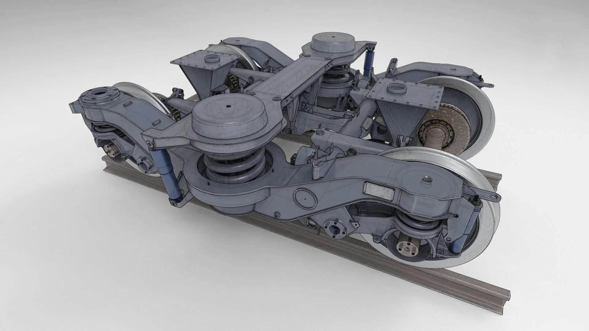
detail and accuracy are most important for the bogies and pantograph, as they are part of the main interfaces in railway engineering,
parts that only become visible in an x-ray view, cutaway view or exploded view must be modeled with the same detail and accuracy,
model should be able to be disassembled down to the smallest construction details,
parts should be modeled both in their welded and pre-welded states,
model should be structured in a way that reflects how it was built in real life,
parts, sub-assemblies and full assemblies should be named in an intuitive way,
additional data should be able to be linked from a database to individual parts or groups of parts,
parts, sub-assemblies and full assemblies must be easily shared with other people from a controlled environment.

Virtual CTO preview video of the Y32 bogie CAD model shown at the CM2018 International Conference on Contact Mechanics (September 2018)
Exterior LiDAR scan of CTO chassis and body
Cutaway view of Y32 bogie CAD model (work in progress)
Handheld 3D scan of skirts and beams fitted to one of the Y32 bogies (isometric view)
Exploded view of Y32 bogie CAD model (work in progress)
PROCESS AND OUTPUT
When I took on this project we knew it was going to be a big challenge, partly because the budget wasn’t fully covered when we started, partly because the Dutch rail industry is not know for its willingness to share information, but also because this would be my first experience with some of the scanning and modeling techniques. In a multi-part blog series about this project, I provide a more in-depth insight into the different phases I went through to realize the Virtual CTO model.
The first phase of the project was about LiDAR scanning, which was needed because hardly any construction drawings were available for the chassis, body and interior of the vehicle. The scanning was done in two sessions, the first one was done outside for the full carriage with and the second one inside focusing on the chassis and interior. I used Z+F 5010x and 5016 laser scanners and all scans were aligned to have everything in the same 3D space. This phase is described in detail in part 1 of the multi-part blog series.
The second phase was about modeling the Y32 bogies. Since a lot (but not all) of the detailed construction drawings were immediately available for the bogies, I decided to start modeling them mainly from those archived drawings. The modeling was done in a parametric CAD environment, as it is much better suited for creating dimensionally accurate 3D models with maximum flexibility in application possibilities. I chose the full cloud based solution of Fusion 360 to because of its user-friendly workflow, Fusion Team Hub and AnyCad technology that makes it possible to import 3rd party CAD files as reference models. This choice makes the Virtual CTO model library very flexible to integrate within the other CAD workflows used at TU Delft. This phase is described in detail in part 2 of the multi-part blog series.
The third phase was about handheld 3D scanning, which was needed for some (custom) parts that were not described in construction drawings and that were also difficult to capture with a lidar scanner. The scanning was done in two sessions, both inside, the first one for the Faiveley AM56 pantograph, and the second one for custom parts of the Y32 bogies and some parts of the chassis. I used a Creaform HandySCAN 700 handheld 3D laser scanner and aligned all scans with the lidar scans. This phase is described in detail in part 3 of the multi-part blog series.
The Virtual CTO project is still a work in progress… I’m still awaiting a significant part of the construction drawings, as well as additional budget to finish the work I’ve started. The preview renders and video on this page give a good general impression of the current status, the screenshot below shows the Fusion Team web interface for the CAD model library I set up to organize all parts and (sub-)assemblies hierarchically. More detail can be found in the multi-part blog series, for which links can also be found in the ‘Featured Posts’ section at the bottom of this page.
Fusion Team web interface for the CAD model library where parts and (sub-)assemblies are hierarchically organized
OUTCOME TESTING
In 2020, in collaboration with the section Railway Engineering, I conducted thorough research into the possibilities to take engineering education at TU Delft to the next level. This included journey mapping for traditional, online and blended learning, and testing simple concepts for a (realtime) 3D learning environment using the Virtual CTO model.
Section from the Journey Map for traditional, online and blended learning at TU Delft, both from a student and teacher perspective
One of the concepts we have been testing is a collaborative VR Learning Environment. We got the chance to test an Early Access version of NVIDIA Holodeck in which we have the full Y32 bogie working as shown earlier on this page. NVIDIA Holodeck is a virtual reality (VR) innovation platform that brings designers, peers, and stakeholders together from anywhere in the world to build and explore creations in a highly realistic, collaborative, and physically simulated VR environment. Sadly we’re not allowed to show any visuals from the Holodeck, because we use it under a full NDA.
Another concept we tested is for making engineering calculations more accessible for students. To demonstrate some of the possibilities of Fusion 360 for engineering calculations, I experimented with FEM simulations, among which for the modal frequencies for a stripped version of the Y32 bogie, as shown below. In addition, CAD design models can also be optimized with Generative Design techniques in Fusion 360.
A third concept we tested is embedding realtime 3D viewers and mobile AR in online course material. The principle is easily demonstrated by uploading a low res version of the Y32 bogie frame to Sketchfab, a platform to publish, share, discover, buy and sell 3D, VR and AR content. With the viewer shown below you can display 3D models on the web, to be viewed on any browser, mobile AR device or Virtual Reality headset.
The last concept that I’m still working on is for serious games in realtime 3D, either embedded on the web or in VR supporting online course material. To demonstrate this I’m currently building a simplified version of a ‘bogie puzzle’ game in Unreal Engine that I’ll show below as soon as it’s done.
Modal frequency test with Y32 bogie frame in Fusion360