JapANESE PAGODA GENERATOR
A STUDY INTO PROCEDURAL MODELING TOOLS FOR HOUDINI AND UNREAL
This page shows the building process and end result of the “Japanese Pagoda Generator” I built during my personal case study into developing flexible and effective procedural modeling tools for Houdini and Unreal. My main goal was to build a polished digital asset that generates clean and efficient geometry, that’s organized in such a way that makes it easy to work with and manually improve upon when necessary.


CHALLENGE
Early 2021 I took a deep dive into procedural modeling in Sean McEwan’s “Procedural Modeling for Production in Houdini” course at CGMA. The course provided some really great assignments to work on, among which a cactus generator (see blog post) and the pagoda generator this study is building forward on. What bothered me, however, was that little or no attention was paid to the actual usability of the procedurally generated geometry for production, often resulting in an overly complex mesh without UVs that would be difficult for other departments to work with. Convinced by the idea that procedural modeling should be able to produce flexible, clean and efficient geometry that is easy to work with, I started this case study to find out how I could make this happen.
Based on experience and research, these are the requirements I felt my Japanese pagoda generator should be able to meet:
single set of (very simple) construction curves and shapes forming an invisible but all-important building structure,
the tool build must be broken down into independent sections and parts, each based on the construction shapes of the building structure,
the model should be assembled from reusable parts by using point instancing to minimize duplicate geometry,
there should be an option to generate a model with proper (and customizable) bevels to add realism when needed,
good quality procedural UVs and a uniform (but also customizable) texel density throughout the entire pagoda,
randomization system for both the 3D orientation during instancing and the UV mapping for each unique part to prevent texture repetition,
a unique part library should be generated in the Content Browser upon baking a pagoda in Unreal, following standard naming conventions,
an easy to read folder structure should be generated in the Outliner upon baking a pagoda in Unreal, following standard naming conventions,
there should be options to enable Nanite for all generated parts, and to automatically assign Unreal materials to groups of generated parts,
the user interface should be logical and intuitive for creating the maximum amount of Japanese pagoda variations with the minimum amount of controls,
preset system that can store individual pagoda variations in separate files, which can be exchanged between Houdini and Unreal,
there should be options to do the shaping of a new pagoda on a light weight or partial pagoda model to improve performance,
all geometry should be generated procedurally (from scratch).
Tool demo of the “Japanese Pagoda Generator” in Houdini 19.5 and Unreal Engine 5.1
RESEARCH
I started the process of building this pagoda generator with researching and analyzing Japanese pagodas. I collected all information I could find about anatomy, structure, shape, patterns, variations and naming and organized the references into a reference board. I decided to limit the generator to two to five story wooden pagodas with square roofs, built on a stone foundation, with one to five optional decorative roofs. To limit the complexity of the first generator version even more, I decided early on to simplify the elaborate wooden support brackets under the roofs (called ‘kumimono’ in Japanese) and, to a lesser extent, some other decorations as well.
Reference board
BUILDING STRUCTURE
After completing the reference board, I created a set of simple construction curves and shapes to build the tool on top of. This workflow prevents me from creating too much consecutive dependencies that will start to work against me at some point. Instead, for each element I can now fall back on the same (very basic) construction curves and shapes that are easy to control, and this also makes the node network a lot cleaner.
The construction shape of my Japanese pagoda is based on a repeatedly extruded single square polygon, forming side polygons that form the basis for walls, roofs, balconies and every other part of the pagoda. By grouping primitives with a similar purpose, specific tool sections know which part of the construction geometry to build on top of. And because this geometry is so simple, it was very easy to implement a control structure for defining the amount of floors, how many floors should have decorative (double) roofs, what the overall shape and dimension of the pagoda should be and whether balconies should be overhanging or internal. The image below shows how these simple construction shapes relate to the final pagoda models that are generated from them.
Building structure of simple shapes vs the final pagoda models generated from them.
SECTIONS, PARTS AND INSTANCES
Once this easily customizable building structure was ready, I broke up the tool build into independent sections, each based on the simple construction shapes of the building structure. What this meant in practice is that I didn’t want any cross-links in the node network between different sections, even though sometimes ‘spaghetti networks’ could be the easiest way to quickly create geometry. Instead, I made each section (except the walls section) directly dependent on the building structure and the user interface parameters, making the whole generator much more flexible for future changes. The image below shows which sections the Japanese pagoda tool is divided into. When using the tool, it is also possible to focus on each of these sections individually using the “Isolate Section” dropdown menu, which speeds it up considerably.
The tool splits the build in independent sections, each based on the construction shapes of the building structure.
Within each section unique parts are constructed procedurally, and target points are defined for instancing these parts multiple times to minimize duplicate geometry. Again, both part dimensions and point positions are directly dependent on the building structure and the user interface parameters. Because each part is constructed independently of any other part, it is very easy to make future changes without breaking anything else. In addition, this workflow also allows for manual adjustments to a part after baking in Unreal (described below), which will then be propagated to the instanced positions automatically.
Within each section unique parts (color coded) are point instanced into multiple positions.
The pagoda node network also shows the independent sections and the point instancing workflow within them.
DETAILS, BEVELS AND RESAMPLING
Initially, I constructed all individual pagoda parts from as little polygons as possible to get the desired shape, with the advantage of keeping the model lightweight. However, realistic renders require proper bevels instead of hard edges. So I’ve been experimenting with two options to create bevels: simple round bevels and creased bevels with subdivision, where the bevel size can be finetuned using bevel multipliers available by part type. As you can see in the image below simple round bevels are still quite lightweight, but for creased bevels with subdivision the polycount increases significantly, which is often not desirable for realtime applications. A side note on beveling: the advantage of working with relatively simple parts is that they are generally much easier to bevel properly, since for complex shapes it can be hard to create bevels with the correct topology, especially procedurally.
Since it might be better for some applications to have more control over the number of polygons for each part, I also implemented a resampling option that uses unique resampling settings per subsection. Custom resampling and beveling give the user the freedom to generate a model in the desired resolution. But because high resolution settings can slow the tool down significantly, these features can be enabled or disabled at any time by using the Quick Output Access buttons “Details” and “Resample” without affecting the overall appearance.
Besides the low-res output, the tool has options per subsection for detailing and beveling, as well as for resampling (to add more resolution when needed).
UV MAPPING AND RANDOMIZATION
During the “Procedural Modeling for Production in Houdini” course at CGMA, I was really surprised to learn that UVs are often ignored by procedural artists (according to Sean’s experience). I knew procedural UVs can be hard to get right, but I imagined that the option to generate good UVs for complex models like this pagoda could be a big quality improvement. Additionally, my experiences with world building in Unreal Engine have learnt me that maintaining a consistent texel density (the amount of texture resolution on a mesh) is a very important requirement in realtime 3D. So, I was determined to implement both.
Fortunately, I had already broken down the Japanese pagoda model into relatively simple parts that are much easier to generate good UVs for as well. While for some parts the SideFX Labs AutoUV node did a pretty good job, for most parts procedurally creating a group with good UV seams gave better and more predictable result in the UV Flatten node. The basic rule I use for all texture UVs is that any edge 90 degrees or sharper should be a UV seam (but not every UV seam needs to be a hard edge).
Before I get into UV layout, just a quick note on my texturing approach for this tool. Since a pagoda is made up of a lot of parts that would actually be made of the same material, and because in realtime 3D it’s better for performance to use as little texture memory as possible, I divided the pagoda model into primitive groups that share the same material definition. For these materials, I used tileable textures as much as possible to make it easier to maintain texel density on larger areas with reasonable texture sizes. These primitive groups with the same material definition can also be made visible by the generator using the “Isolate Material” feature that’s available in the tool’s user interface (the image on the right shows an example of its output).
UV Layout is the part of UV mapping that packs UV islands into UV space. It uses three important transforms:
Orientation in this case is determined by my personal rule of placing the longest edge along the U-axis.
Scaling is where texel density comes into play. The tutorials by Anthony O’Donnell, Leonardo Lezzi and Malcolm Andrieshyn explain the concept better than I ever could. I implemented it with the SideFX Labs Texel Density node. The idea is that you set the desired texel density in this node first by entering a base resolution (the default I chose for the entire tool is a 512 x 512 texture mapped onto a 100 x 100 cm plane, resulting in a texel density of 5,12 texels per cm). Then by entering the actual texture resolution for each part, the UV islands are scaled in such a way that your defined texel density (5,12 in the default case) is always maintained and will therefore be consistent across the entire pagoda. The overall texel density and texture resolution per material can be set via the tool’s user interface.
Position is where randomization becomes relevant. Randomization is the perfect way to texture as many parts as possible with the same tileable texture without anyone noticing. The first part of my randomization strategy is to randomly orient the same part in 3D in as many ways as possible so that identical parts still look different next to each other (because it shows a different part of the texture space). I implemented this by randomizing the Normal and/or Up vectors for the target points used for instancing. The second part of my randomization strategy is to randomly position UV islands in UV space so each unique part uses a different section of the same texture (this way you don’t notice it when the same texture is used over and over again by different parts). I implemented this with a UV Transform node by randomizing the translate values. A seed value that influences all randomization operations can be set via the tool’s user interface.
An additional factor I took into account is the padding between UV islands. The optimal shell padding is depending on how much you expect the texture to be mipped down (smaller mips = bigger padding). This means that for bigger texture resolutions the shell padding needs to be bigger as well. The shell padding can be set per material via the tool’s user interface (the default is 8px on a 2k texture).
Because UV mapping is the most expensive part of the entire generator, it can be enabled or disabled at any time using the Quick Output Access button “UVs”. This significantly reduces the generator's cook time.
A note that has to be made about this way of texturing is that it results in a lot of overlapping UVs, which looks crazy in UV space, but when the randomization is done well, no one will notice it in 3D space. The images below demonstrate how it looks when you have good UV mapping and randomization, what happens when randomization is turned off, and how it looks when texture resolutions are too low (the image on the right shows the textures that are used to visualize this). In all cases texel density is maintained across the entire pagoda.
An example of parts that share the same material definition.
Size chart “UV Checker Texture” by Thomas Schmall
No texture repetition when randomization is on for both the 3D orientation during instancing and the UV mapping for each unique part (with texel density set to 5,12 texels per cm).
When randomization is turned off, an ugly texture repetition appears (while texel density remains uniform).
When texture resolutions are too low, texture repetition appears as well (while texel density remains uniform).
To limit the complexity of the first generator version, I decided to stick with this single texture UV channel (uv1) and an optional lightmap UV channel (uv2, for non-Nanite geometry in Unreal, mapped with different rules). This only supports a single material layer per part though. Therefore, when you would like to add dust or other unique details, it could be beneficial to add a second texture UV channel (uv3) with atlas UVs per group of parts nicely layed out without any overlap. Atlas textures could then be used for masking in other tileable textures on top (like dust), but they can be much lower in resolution because they’re only used for the masks. The way the tool is set up now, makes it pretty straightforward to add improvements like this.
ControlLing the OUTPUT IN UNREAL
With most of the model completed, the next step was to control the output in Unreal Engine. Fortunately, the release of Houdini Engine for Unreal version 2 opened up a range of possibilities to realize my goal to organize the HDA output in Unreal in such a way that makes it easy to work with and manually improve upon when necessary.
First, an HDA can now generate a unique part library in the Content Browser upon baking in Unreal. In this part library unique parts are separated out as Static Meshes by packing them in Houdini. They are named according to standard naming conventions, built with the correct build settings, have Nanite enabled when desired, and may have an Unreal material assigned where needed, just by sending along some special attributes. The result is exactly how you would set it up manually, making it possible for an art department to build forward on a procedurally generated model. For example, you can now take an individual part and bring it into ZBrush for detailing and then replace it with the new version in Unreal. Or replace the material assignment for just one part. Any adjustments will be propagated to all instances in the assembly automatically.
Second, an HDA can now generate an easy to read folder structure in the Outliner upon baking in Unreal. In this folder structure all folders and Instanced Static Mesh actors have clear names according to standard naming conventions and they point to the unique parts library created in the Content Browser, just by sending along a bunch of special attributes. The baked result could then be converted into a Packed Level Actor (Blueprint) containing the entire assembly in a single actor. This makes it possible to use a specific design over and over again in your scene at little extra cost.
When using attributes to control properties of either the instancer or the instanced mesh when using packed primitives, it is very important to pay attention to the "location" of the attributes. An attribute that is applied before packing will be applied to the generated mesh, whereas an attribute applied after packing will only be applied to the instancer.
The image on the right shows a sample from the node network that adds these special attributes to control the output in Unreal. The image below shows an example of that output, where the highlighted Instanced Static Mesh actor in the Outliner uses the highlighted Static Mesh from the Content Browser for instancing the highlighted parts visible in the Viewport.
These Unreal specific features can be enabled or disabled at any time using the Quick Output Access buttons “Unreal” and “Triangulate”.
Sample from the node network that adds special attributes to control the output in Unreal Engine.
Example of the Japanese Pagoda Generator HDA output in Unreal Engine 5.1 after baking
USER INTERFACE
To build a user interface, I always start right away by creating control parameters in a CTRLS node (null). This forces me to design the tool with logical controls in mind, makes visualizing dependencies in the node graph very easy and it also makes it very easy to promote these control parameters as soon as I want to turn the tool into an HDA.
Just like in the procedural build itself, I’ve broken up the user interface into separate tabs for independent sections. Control parameters that won’t do anything in a certain state are greyed out and locked to avoid confusion. Parameters that need explanation have tool tips, but most parameters speak for themselves.
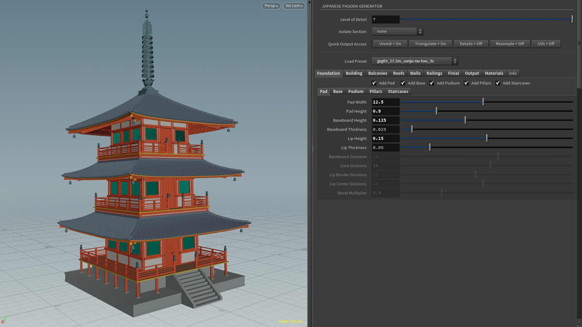
At the top of the user interface I've added several options that make it possible to do the shaping of a pagoda on a light weight or partial model to improve performance:
The Level of Detail slider makes it possible to build up the pagoda from little to full detail (see image on the right),
The Isolate Section dropdown menu makes it possible to focus on a single section while all others are turned off (see corresponding section above),
The Quick Output Access buttons ‘Unreal - Triangulate - Details - Resample - UVs’ make it possible to completely disable specific features, which is recommended for most of the shaping process (see corresponding sections above),
The Preset dropdown menu makes it possible to switch between built-in or custom presets quickly, and presets can also be exchanged between Houdini and Unreal (see below).
You can use any combination of these options to work on only that part of the pagoda that is relevant to the stage you are in.
The image below shows a walk-through of the user interface in both Houdini and Unreal Engine. Getting both user interfaces to behave in a similar way was an added challenge, as some parameters that work fine in Houdini behave differently in Unreal or are not supported at all. Baking in Unreal even behaved differently in normal streaming levels and world partition levels.
Partially shaping a pagoda in a lower detail level reduces build time significantly
User Interface walk-through of the Japanese Pagoda Generator HDA in Houdini 19.5 vs Unreal 5.1
PRESETS
A complex model like this Japanese pagoda requires a lot of control parameters to be able to create useful variations. That's why I quickly became to realize that a good preset system would be indispensable for a tool like this. And since Houdini’s preset features are rather limited for custom HDA’s, I decided to setup my own preset system by using Python scripts to read/write parameter values from/to a json-file.
In order for the preset system to work, the control parameter ‘Preset Directory’ has to be defined in the UI first. This gives the system the info where to look, and causes the ‘Load Preset’ drop down menu to list all presets already available. Selecting one of these options will trigger the read script to read and convert the contents of the json-preset file, and replace all control parameters in the UI with new values. For saving, you also have to set the ‘Preset Name’ parameter. Upon clicking the ‘Save Preset’ button, the write script will run through all parameters in the HDA, but skip over the ones that are marked for exclusion. The script will then convert the parameters into a json-format and write them away to a json-file in the preset directory, after which it becomes available in the ‘Load Preset’ dropdown menu as well.
The advantage of a json file based preset system like this is that the HDA in Unreal can point to and read the same preset directory, making it possible to prepare your models in Houdini, which is still a lot faster than in Unreal. In addition, the preset files are very small and can easily be shared with another artist. Below (and on the top of this page) is an impression of the eight built-in presets that demonstrate the variety of 3D models that can be generated with the Japanese Pagoda Generator. With these presets you can quickly find the desired type and size of pagoda, so that you can realize your own pagoda design faster.
Impression of the variety of 3D models that can be generated with the Japanese Pagoda Generator.
CLOsing words
It was a lot of fun and very rewarding working on this Japanese Pagoda Generator and I am very proud of how it turned out, completing every item on my requirements list. Procedural modeling is incredibly powerful! And, I'm happy to conclude that it can produce flexible, clean and efficient geometry that is easy to work with!
But what would I do differently next time? One thing I should have considered even more from the start is performance. I implemented several options to speed up the tool while working on a new pagoda design, resulting in cook times between a few seconds and a few minutes (depending on the complexity of the build). But using Compile Blocks, for example, could have given the generator that extra boost to make it significantly faster (possibly at least 50-80%). However, since I came to this conclusion quite late in the process, the limitations in implementing it created so much extra work that I decided to save it for another time.
Another thing I didn’t look into is the procedural generation of the textures and materials themselves. It would be an interesting topic for a future study to find out if and how this can be integrated into the tool, so a fully textured and shaded pagoda asset could be generated with a single HDA (in both Houdini and Unreal).